Brushless Vs Brushed DC Motors: When and Why to Choose One Over the Other
DOWNLOAD PDF

Get valuable resources straight to your inbox - sent out once per month
We value your privacy
Introduction
Many motion control applications use permanent magnet DC motors. Since it is easier to implement control systems using DC motors compared to AC motors, they are often used when speed, torque, or position needs to be controlled.
There are two types of commonly used DC motors: Brushed motors, and brushless motors (or BLDC motors). As their names imply, DC brushed motors have brushes, which are used to commutate the motor to cause it to spin. Brushless motors replace the mechanical commutation function with electronic control.
In many applications, either a brushed or brushless DC motor can be used. They function based on the same principles of attraction and repulsion between coils and permanent magnets. Both have advantages and disadvantages that may cause you to choose one over the other, depending on your application’s requirements.
DC Brushed Motors
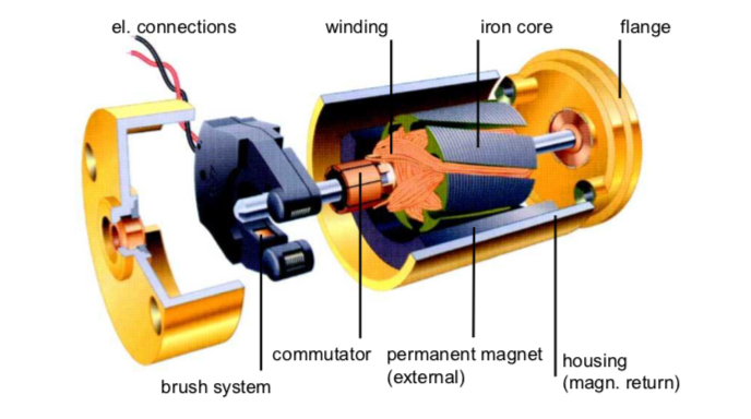
DC Brushed Motors (image by maxon group)
DC motors use wound coils of wire to create a magnetic field. In a brushed motor, these coils are free to rotate to drive a shaft – they are the part of the motor that’s called the “rotor”. Usually the coils are wound around an iron core, though there are also brushed motors that are “coreless”, where the winding is self-supported.
The fixed part of the motor is called the “stator”. Permanent magnets are used to provide a stationary magnetic field. Normally these magnets are positioned on the inner surface of the stator, outside of the rotor.
In order to create torque, which makes the rotor spin, the magnetic field of the rotor needs to continuously rotate, so that it’s field attracts and repels the fixed field of the stator. To make the field rotate, a sliding electrical switch is used. The switch consists of the commutator, which is typically a segmented contact mounted to the rotor, and fixed brushes which are mounted to the stator.
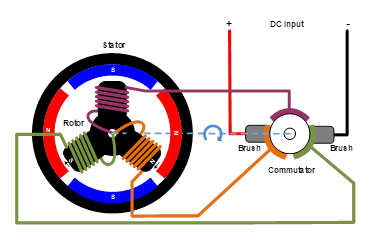
As the rotor turns, different sets of rotor windings are constantly switched on and off by the commutator. This causes the coils of the rotor to be constantly attracted and repelled from the stator’s fixed magnets, which makes the rotor spin.
Since there is some mechanical friction between the brushes and commutator – and since it is an electrical contact, it generally cannot be lubricated – there is mechanical wear of the brushes and commutator over the lifetime of the motor. This wear will eventually reach a point where the motor no longer functions. Many brushed motors – especially large ones – have replaceable brushes, typically made of carbon, which are designed to maintain good contact as the wear. These motors require periodic maintenance. Even with replaceable brushes, eventually the commutator also wears to the point that the motor must be replaced.
To drive a brushed motor, DC voltage is applied across the brushes, which passes current through the rotor windings to make the motor spin.
In cases where rotation is only needed in one direction, and speed or torque doesn’t need to be controlled, no drive electronics at all are required for a brushed motor. In applications like this, the DC voltage is simply switched on and off to make the motor run or stop. This is typical in low cost applications like motorized toys. If reversal is needed, it can be accomplished by using a double pole switch.
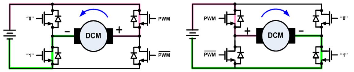
To facilitate control of speed, torque, and direction, an “H-bridge” composed of electronic switches - transistors, IGBTs, or MOSFETs - is used to allow the motor to be driven in either direction. This allows the voltage to be applied to the motor in either polarity, which makes the motor rotate in opposite directions. The motor speed or torque can be controlled by pulse width modulating one of the switches.
Brushless DC Motors
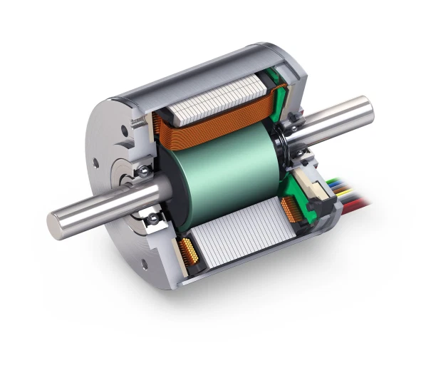
Brushless DC Motors (image by maxon group)
Brushless DC motors operate on the same principle of magnetic attraction and repulsion as brush motors, but they are constructed somewhat differently. Instead of a mechanical commutator and brushes, the magnetic field of the stator is rotated by using electronic commutation. This requires the use of active control electronics.
In a brushless motor, the rotor has permanent magnets affixed to it, and the stator has windings. Brushless motors can be constructed with the rotor on the inside, as shown above, or with the rotor on the outside of the windings (sometimes called an “outrunner” motor).
The number of windings used in a brushless motor is called the number of phases. Though brushless motors can be constructed with different numbers of phases, three phase brushless motors are the most common. An exception is small cooling fans that may use only one or two phases.
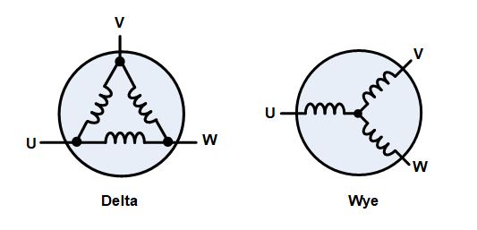
The three windings of a brushless motor are connected in either a “star” or a “delta” configuration. In either case, there are three wires connecting to the motor, and the drive technique and waveform is identical.
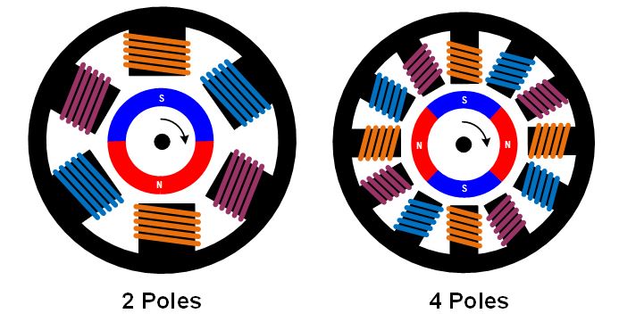
With three phases, motors can be constructed with different magnetic configurations, called poles. The simplest 3-phase motors have two poles: the rotor has only one pair of magnetic poles, one North and one South. Motors can also be built with more poles, which requires more magnetic sections in the rotor, and more windings in the stator. Higher pole counts can provide higher performance, though very high speeds are better accomplished with lower pole counts.
To drive a three phase brushless motor, each of the three phases needs to be able to be driven to either the input supply voltage or ground. To accomplish this, three “half bridge” drive circuits are used, each consisting of two switches. The switches can be bipolar transistors, IGBTs, or MOSFETs, depending on the voltage and current required.
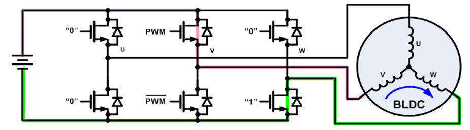
There are a number of drive techniques that can be employed for three phase brushless motors. The simplest is called trapezoidal, block, or 120-degree commutation. Trapezoidal commutation is somewhat similar to the commutation method used in a DC brush motor. In this scheme, at any given time, one of the three phases is connected to ground, one is left open, and the other is driven to the supply voltage. If speed or torque control is needed, usually the phase connected to the supply is pulse width modulated. Since the phases are switched abruptly at each commutation point, while the rotor rotation is constant, there is some variation of torque (called torque ripple) as the motor rotates.
For higher performance, other commutation methods can be used. Sine, or 180-degree, commutation drives current thorough all three motor phases all of the time. The drive electronics generates a sinusoidal current though each phase, each shifted 120 degrees from the other. This drive technique minimizes torque ripple, as well as acoustic noise and vibration, and is often used for high performance or high efficiency drives.
To properly rotate the field, the control electronics need to know the physical position of the magnets on the rotor relative to the stator. Often, the position information is obtained using Hall sensors that are mounted to the stator. As the magnetic rotor turns, the Hall sensors pick up the magnetic field of the rotor. This information is used by the drive electronics to pass current through the stator windings in a sequence that causes the rotor to spin.
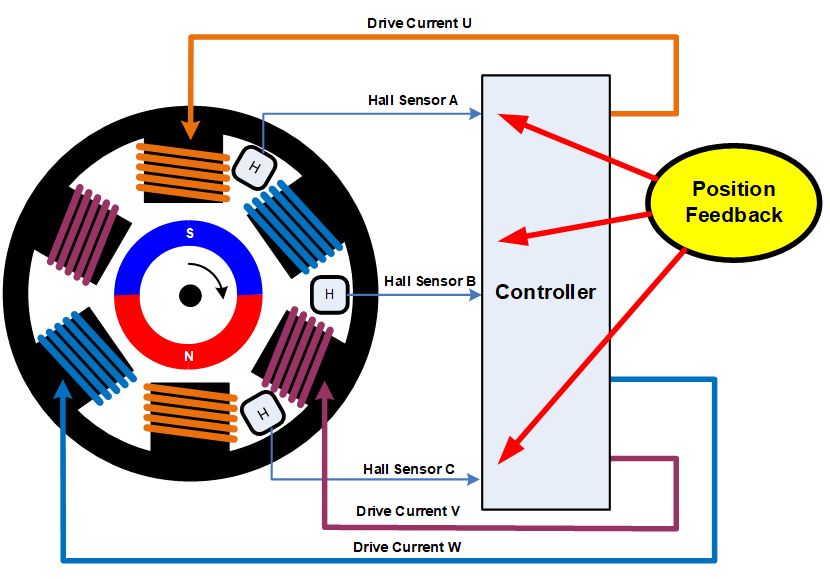
Using three Hall sensors, trapezoidal commutation can be implemented with simple combinational logic, so no sophisticated control electronics are needed. Other commutation methods, like sine commutation, require a bit more sophisticated control electronics, and usually employ a microcontroller.
In addition to providing position feedback using Hall sensors, there are various methods that can be used to determine the rotor position without sensors. The simplest is to monitor the back EMF on an undriven phase to sense the magnetic field relative to the stator. A more sophisticated control algorithm, called Field Oriented Control or FOC, calculates the position based on rotor currents and other parameters. FOC typically requires a fairly powerful processor, as there are many calculations that have to be performed very quickly. This, of course, is costlier than a simple trapezoidal control method.
Brushed and Brushless Motors: Advantages and Disadvantages
Depending on your application, there are reasons why you might choose to use a brushless motor over a brushed motor. The following table summarizes the main advantages and disadvantages of each motor type:
| Brushed motor | Brushless motor | |
| Lifetime | Short (brushes wear out) | Long (no brushes to wear) |
| Speed and Acceleration | Medium | High |
| Efficiency | Medium | High |
| Electrical Noise | Noisy (bush arcing) | Quiet |
| Acoustic Noise & Torque Ripple | Poor | Medium (trapezoidal) or good (sine) |
| Cost | Lowest | Medium (added electronics) |
Lifetime
As previously mentioned, one of the disadvantages of brushed motors is that there is mechanical wear of the brushes and commutator. Carbon brushes in particular are sacrificial, and in many motors they are designed to be replaced periodically as part of a maintenance program. The soft copper of the commutator is also slowly worn away by the brushes, and eventually reach a point where the motor will no longer operate. Since brushless motors have no moving contacts, they do not suffer from this wear.
Speed and Acceleration
Brushed motors rotational speed can be limited by the brushes and commutator, as well as the mass of the rotor. At very high speeds, the brush to commutator contact can become erratic, and brush arcing increases. Most brushed motors also use a core of laminated iron in the rotor, which gives them large rotational inertia. This limits the acceleration and deceleration rates of the motor. It is possible to build a brushless motor with very powerful rare earth magnets on the rotor, which minimizes the rotational inertia. Of course, that increases the cost.
Electrical Noise
The brushes and commutator form a kind of electrical switch. As the motor turns, the switches are being opened and closed, while significant current is flowing through the rotor windings, which are inductive. This results in arcing at the contacts. This generates a large amount of electrical noise, which can get coupled into sensitive circuits. Arcing can be somewhat mitigated by adding capacitors or RC snubbers across the brushes, but the instantaneous switching of the commutator always generates some electrical noise.
Acoustic Noise
Brushed motors are “hard switched” – that is, current is abruptly moved from one winding to another. The torque generated varies over the rotation of the rotor as the windings get switched on and off. With a brushless motor, it is possible to control the winding currents in a way that gradually transitions current from one winding to another. This lowers torque ripple, which is a mechanical pulsation of energy onto the rotor. Torque ripple causes vibration and mechanical noise, especially at low rotor speeds.
Cost
Since brushless motors require more sophisticated electronics, the overall cost of a brushless drive is higher than that of a brush motor. Even though a brushless motor is simpler to manufacture than a brushed motor, since it lacks brushes and a commutator, brushed motor technology is very mature and manufacturing costs are low. This is changing as brushless motors become more popular, especially in high volume applications like automotive motors. Also, the cost of electronics, like microcontrollers, continues to decline, making brushless motors more attractive.
Summary
Due to declining costs and better performance, brushless motors are gaining in popularity in many applications. But there are still places where brushed motors make more sense.
Much can be learned by looking at the adoption of brushless motors in automobiles. As of 2020, most motors that are running whenever the car is running – things like pumps and fans – have moved from brushed motors to brushless motors for their increased reliability. The added cost of the motor and electronics more than makes up for the lower rate of field failures and decreased maintenance requirements.
On the other hand, motors that are operated infrequently – for example, motors that move power seats and power windows – have remained predominately brush motors. The reasoning is that the total run time over the life of the car is very small, and it is very unlikely that the motors will fail over the life of the car.
As the cost of brushless motors and their associated electronics continues to decrease, brushless motors are finding their way into applications that have traditionally been held by brushed motors. As another example from the automotive world, seat adjustment motors in high end card have been adopting brushless motors because they generate less acoustic noise.
Technical Forum
 Latest activity 2 days ago
 2 Comments
Latest activity 4 days ago
2 Comments
Latest activity 2 weeks ago
3 Comments
2 Comments
Latest activity 4 days ago
2 Comments
Latest activity 2 weeks ago
3 Comments
Log in to your account
Create New Account