

Today we talk something about SWR, what it really is, why it is important to know about it and measure it regularly, how it calulate, what value is already critical and what happens if it is not equal to 1:1. We will not define it purely mathematically (who is interested in the Internet is a lot of information) but practically from the point of view of the radio amateur even if the basic definitions are not avoidable.
So what is SWR
SWR is short mark for Standing Wave Ratio. So it’s some non-dimensional unit that tells us about whether and if so in what proportion there is a standing wave in the RF feeder. This answer brings with it additional questions, so let’s first define the basic characteristics that are associated with it.
First, a little theory
If we imagine the classic connection of the transceiver with a coaxial cable from one side connected to its antenna connector and on the other side connected to the antenna then we get a system where Transceiver (in TX mode) is a source of RF power, coaxial cable is feed line and antenna as a load. Ideally, the entire RF energy from the transceiver passes through the feeder into the antenna where the whole glows into the surrounding environment. However, since we live in the real world and not ideally as you rightly guess, it will not be so easy.
So how is it
There are even more complexities in the real world than meets the eye. If we dealt with them all from the very beginning, we would probably get tangled up and not move anywhere. Therefore, we will make it easier at the beginning by thinking about an antenna that radiates almost all the energy we transport to it. We will not deal with its resonant frequency or losses in its matching elements, or whether it is horizontally polarized or vertically, nor will we be interested in whether it is symmetrical or what system of ground radials or anything similar. As you can see, there are so many questions about the antennas that we would really get involved and I don’t want that. Antennas are a very large chapter in themselves, so now we will only be interested in one parameter and that is its impedance.
In order to transport as much energy as possible from the transceiner to the antenna, 3 conditions must be met. The impedance of all three components (transceiver, feedline, antenna) must be the same or the feeder may have a different impedance, but in that case it will depend on its exact length depending on the frequency of RF energy, but we will not deal with this now. Some might oppose the fact that we can use non-coaxial power supply or impedance transformers, but in this case we will consider plugging transceiver, coaxial cable and antenna with the same impedance. So, if impedances are the same the energy from the transceiver passes through the feeder to the antenna where almost the whole glows. Not all, because in the real world conductivity and dielectric losses of coaxial cable, connectors and antenna itself apply. However, these losses will be minimal if we choose quality materials and we will be satisfied with the result.
What happens in the event of a different impedance
However, if there is a situation where the impedances are not the same (e.g. the impedance of the antenna will be different from that of the transceiner and the coaxial cable), there will be a phenomenon that we call standing waves. RF energy that comes from the transceiner to the antenna can be seen as a wave in the direction of the antenna, this energy has a certain power and we will characterize it as forward power. If the antenna has a different impedance a certain part of this wave is not radiated by the antenna but bounces back to the transceiver. We will characterise this reflected energy as a reflected power. By spreading the whole performance in one direction and its reflected part of the other, we are getting the aforementioned standing wave. At first glance, it is clear that forward power will always be greater than reflected. Even if the whole part is reflected, it will be at most the same, although in the real world it will always be smaller than direct because of the losses mentioned above.
Why it should mind
We could tell that we don’t mind any part of it always being radiated, so basically after a few cycles, the bulk of it will still be radiated. However, this does not apply in the case of a coaxial cable with a conventional dielectric. Standing waves do not like the coaxial cables or dielectric used between the middle conductor and shield. The larger the SWR, the greater the losses in the coaxial cable, i.e. our energy is suppressed and never radiated into space but turns into heat. Acknowledge yourself that transceiver as a heat generator and coaxial cable as a heating element is not exactly why we are fascinated by this hobby. In order to somehow clearly characterise this phenomenon by number, the term STANDING WAVE RATIO – SWR
How SWR is characterized mathematically
SWR can be calculated from different variables (impedances, voltages, powers …) in our case we are talking about power so mathematically it is about this:
SWR = (1+√(Pr/Pf)) / (1-√(Pr/Pf))
Pr – Is reflected power
Pf – Is forward power
In case all the power is radiated we are talking about SWR 1:1. It cannot be less than 1:1 because there can be no less power than none, and any larger number than 1 means that there is a standing wave in the system. For example, if SWR = 3:1 means that 25% of the power is reflected back. If SWR = 2:1 it is only 11%.
SWR measurement
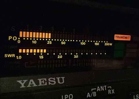
We use SWR meters or antenna analysers to measure SWR. I already wrote about antenna analyzers in a previous article. SWR meters are essentially passive forward and reflected power meters (although they actually measure voltages and their scales are seduced in watts but sometimes at other times). They are installed between the transceiver and the antenna. This meter shall use the energy of the transceiver in TX mode to be measured in both directions (both forward and reflected) and the SWR value shall be determined accordingly. Today, most transceivers already have a built-in SWR meter, so we can see the SWR value directly during transmission, and in case it starts to change dramatically, we know that something is wrong with the transceiver, the feeder or the antenna.
What types of SWR meters are used
The most common analog SWR meters are cross and single with a switch.
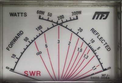
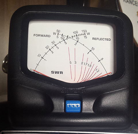
The SWR cross meter works by implementing two analog measuring instruments into one body of the instrument, their indicators oriented against each other and crossed in the case of a vimeo. Both indicators have a scale in watts so they’re basically two wattmeters. One measures forward and the other reflected power. Since SWR is determined by the ratio of both of these performances on the instrument, there is still a third scale which is graduated directly in the SWR units and at the point where the indicators of both watt-metres are crossed, we see the specific SWR value. However, this method is less accurate, especially at low SWR values, where the reflected power is already minimal.
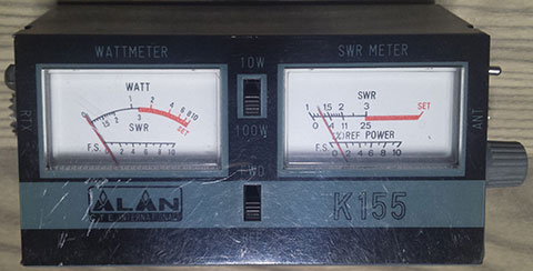
Another type of analog SWR meter is a simple meter with a forward and reflected power switch. This method of measurement uses a regulatory element that influences the amplification of the measurement itself. It is an analog gauge which, in the forward power position (FWD), measures in the direction of the antenna and in the reflected power position in the opposite direction. The regulatory element in the form of a potentiometer regulates the gain or attenuation of both measurements and it is important that this happens in equal proportions in both directions. The meter itself is not in watts units because it is not even possible as the potentiometer directly affects the angle of indicator. The measurement shall be carried out in such a way that the SWR meter is connected between the transceiver and the antenna and the transceiver is set to a mode where only the transceiver comes out of the transceiver and its amplitude is not affected by the modulation route. This is the most common FM or CW mode. At a stable power value, the set SWR meter is set to FWD and adjusted to maximum by the indicator vying control element (often marked with a SET symbol). Then we switch the measurement direction to the REF position, but we do not touch the control element anymore. The meter indicator angle changes and we read the SWR value directly on the scale.
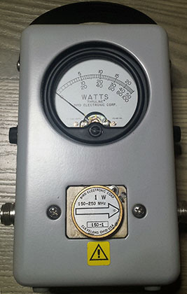
Another way to measure SWR is to connect between the antenna and the transceiver wattmeter on which we subtract the power in one direction then connect it in the opposite direction (we will change the connectors marked for TRX and ANT between each other) and again measure the power. In doing so, we have two performances one in a forward line and the other in a reflected direction. Once added to the formula above, we get the SWR value. It is a less elegant method of measurement and requires more time and action and, above all, that the figure is accurate, it must not happen that the output power of the transceiler changes during the resuasion of the power measurement direction (when we are forced to turn off TX transceiler mode). For this reason, Bird produces a watt-meter which directly allows me to change the direction of measurement during TX mode by turning the so-called “BIRD element”. But the lengthy calculation process of both measured performances still awaits us even with the use of such a measuring device. However, we can help with countless online calculators on the Internet or an app on a smartphone where we only enter forward and reflected performance and instantly know the value of SWR.
In the case of digital SWR meters controlled by a microcontroller, we do not need to do any calculations or adjust anything just to subtract the value directly from the SWR meter display.
If the transceiver or RF amplifier is equipped with its own SWR measurement, we are not interested in this concern and we can see the SWR directly on the transceiver or RF amplifier display.
In addition to the loss of radiated power, there is still something
The larger the SWR the smaller the radiated power. However, in addition to the loss of valuable RF performance, there is another problem, which is the strain of the power RF transistor. The larger the SWR the more the end transistor is stressed and threatened with permanent damage. Modern Transceivers and end amplifiers have built-in protections that constantly monitor current SWR systems and automatically turn transmission power or block the device to high SWR errore when it rises to dangerous levels. What is this critical value of SWR is not clearly determined. It depends on the manufacturer and the topology of the wiring itself, cooling of used transistors, etc. However, in general, the more massive the end stage (in terms of rated output), the higher the threshold. E.g. Yaesu FT897 is a small 100W transceiver with little cooling and not extra oversized transistors of the RF power block. Its limit the output power when it takes up protection of high SWR is set somewhere around 1.5:1. The Yaesu FT1000MP transceiver is a large desk top transceiver with a power output of also 100W but the robust cooler and oversized RF stage transistors have this value set up to SWR about 2.5:1.
Tuners, transmatches …
There are various tuners or transmatches that can be used and connected between antenna and transceiver. That tune the Transceiver – Tuner way to SWR 1:1. However, this is only good for the protection of Transceivor. We will not suffer from an output transistor and will not take up protection reducing output power, but remember that you will not eliminate these losses using a tuner or more in the system, and that is, the losses of the tuner, which tend to be very large. If it is necessary to use the tuner only so that an antenna is connected directly to it with the shortest possible feeder. Here they comply with the so-called remotely controlled tuners located as close as possible to the connector of the antenna (often located on the roof) and controlled manually remotely or automatically by electronics located directly in the tuners. The second option is to place the tuner near the operator directly in the hamshack and use a feeder whose high SWR does not be so losses.
Feeder with small losses at high SWR
There are also feeders that do not weigh as heavily on high SWR as coaxial cables. They’re symmetrical window line feeders and good old ladder line. Here we can really use an antenna with a different impedance than transceiver, but we need to use as a symmetric feeder a symmetric tuner located in hamshack right next to the transceiver. With this tuner we will ensure impedance on the side of the transceiver 50 ohms ie there will be no standing waves on the coaxial connection Tuner – Transceiver. Another thing that such a tuner will provide us with is the transition between the symmetrical system of the feeder and the asymmetrical system of the transceiver. However, standing waves occur on the antenna -Tuner connection where, if a symmetrical feeder is used, there will be no high losses because this type of feeder is also suitable for heavy SWR loads. However, be ware of the type and setting of the tuner. With the wrong type or poor setting, we can get to a very high level of losses in the tuner itself. I recommend using only L network LC – CL switchable tuner therefore there is no PI network formed as CLC which is the most cheap manual tuners. However, this is already beyond the scope of this article.
Why so many worries when it’s enough for the system to have the same impedance
At the beginning, we said that if we keep the same impedance in the source, in the feeder and also in the load, we will not get a stationary wave and radiate the maximum output power. The impedance of the Transceiver antenna output is determined by the manufacturer (in most case it is 50 ohms). If we use the coaxial cable as a feeder whose nominal impedance is also 50 ohms, we do not have to worry about its exact length, which would somehow affect whether there is a stationary wave in the system or not. So where’s the problem? We only have the last piece of the puzzle left, and that’s the antenna.
Load with impedance of 50 ohms
If we add a residual non-induction load of 50 ohms instead of an antenna, there will be no really standing wave in such a system. Most of the power gets into the above load and there it turns into heat. We call such a load a dummy load and use it for measurement and adjustment purposes. Such a load at least radiates to the surroundings, so when adjusting we do not disturb the surroundings and even the applicable regulations do not allow us to make settings other than antenna settings to a different load than dummy ones.
So why don’t we use an antenna with an impedance of 50 ohms and it’s a no problem
This is, of course, an excellent idea but difficult to implement. The antenna does not behave like a residual non-induction load which has the same impedance at all frequencies of its usability spectrum, but the antenna has a different impedance at each frequency. Therefore, antennas are designed to resonate precisely at frequencies of their use where the impedance is usually 50 ohms (if they are antennas designed to connect a coaxial feeder). So-called monoband antennas are produced which are designed for only one band, i.e. if we use them on this band they will have an impedance close to 50 ohms and there will be no standing wave in the feeder. As a rule, such an antenna must be adjusted by some adjusting element when assembling, and a transceiver and SWR meter are sufficient to help us. If it is an antenna e.g. for the 15m band i.e. 21MHz, we will first decide where to operate it and whether it is in CW mode or SSB. If we decide that in the SSB we know that the 15m band has a frequency segment enabled for SSB operation from 21,150 to 21,450 MHz. We choose the center of this band which is 21.300MHz here we set the transceiver and measure the SWR. With the antenna adjusting element, we try to fine-tune the antenna to as little SWR as possible. Then we will test the upper and lower limits of the frequency band (in our case 21,150 and 21,450 MHz) where of course the SWR will be higher but if it is roughly the same we are done. If not fine-tuned so that at both ends of the frequency band there is roughly the same SWR value and the best will be somewhere in the middle.
There are also multiband antennas i.e. it is an antenna where several bands are contained. Such antennas must be tuned for each band separately, taking care not to tune the previous one by tweaking the next band. It is also possible to use a SWR meter here, but in this case it is easier and more practical to adjust with an antenna analyzer.
Is a good SWR a guarantee of maximum radiated power?
I will probably disappoint you, but it is not. Many radio amateurs think that the most important thing for meeting the maximum radiated power is SWR close to 1: 1. However, this is a mistake because a good SWR only tells us that we managed to transport a large part of the RF energy from the transceiver to the antenna input. However, it does not say anything about whether this energy will really be radiated. If you don’t believe me, try to connect an dummy load instead of an antenna and try to call. I guarantee you that SWR would be excellent and even so, your neighbor will hear you as much as possible.
Conclusion
The SWR meter should be the basic measuring instrument of each radioamateur. Without it, no budding radio amateur can start because “shooting blind” doesn’t really good here. Today, however, most transceivers already have a built-in SWR meter which greatly simplifies the operation itself as well as the antenna adjustment. Finally, I would add that each SWR meter has a basic two parameters that we must not overlook. One is the power for which it is designed and the other the spectrum for which it is made. We cannot adjust the VHF antenna with a short-wave SWR meter, and when adjusting the SWR, we must make sure that we do not release more power than the one for which it is designed through the SWR meter.
To the question that was answered at the very beginning What is SWR already know the answer and the second question whether it is so important we know the answer as well. It is and it is not. In the case of the use of a symmetric feeder, which has small losses under load of high SWR, this is not so important. But if we’re talking about an unsymmetrical coaxial cable, that’s where it’s important.