Update 2022-10-31: Vojtech, OK1IAK pointed out that the circuit may increase the amount of harmonic content of your output signal. I did some preliminary analysis of this, see below for details.
Update 2018-05-14: Hamshop.cz is now offering a complete kit of TinySWR, i.e. a PCB and all required parts at a very fair price (ca. 5 EUR).
Note: If you ordered a PCB from OSH Park before October 24, 2017, you have to fix one minor bug in the layout by means of a short piece of wire, see below for details.
A tiny SWR and RF power indicator for QRP transceivers - just 20.98x14.38 mm!
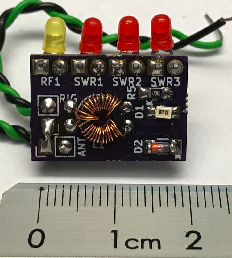
This is a simple SWR and RF power indicator for QRP transceivers. It will work well with 1...5 W rigs.
The circuit is based on a design by Hans Steinort (DF3OS), see http://www.sp5jnw.sem.pl/konstrukcje/atudf3oshtm/atudf3oseng.pdf, with improvements from Dieter Engels (DJ6TE) and Hannes Hiller (DL9SCO).
I changed the values of certain components, modified the LED array, and designed a SMD PCB so that it is easier to assemble.
The PCB can be ordered from OSH Park at a very fair price (as of writing: USD 2.30 for three boards including shipment to Germany).
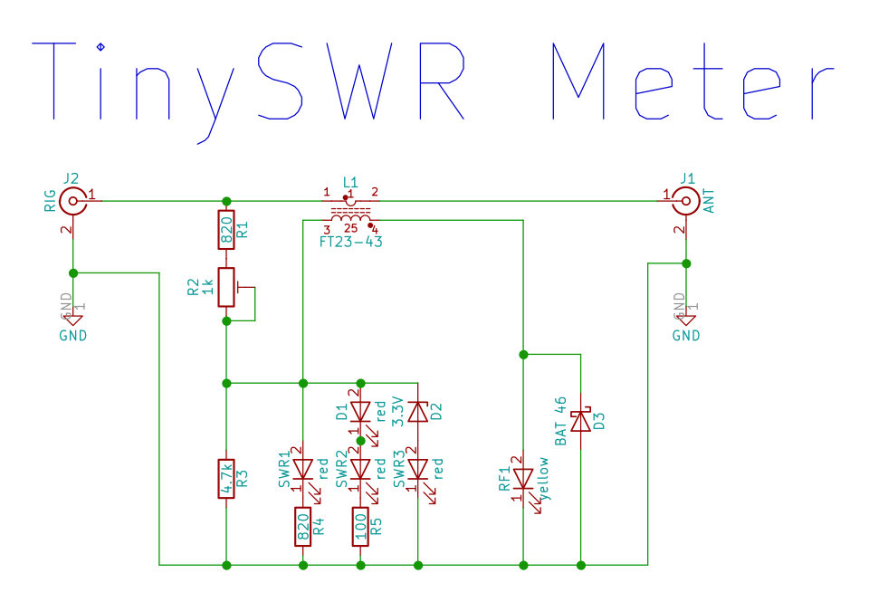
The schematic can be found in PDF format .
The circuit uses a standard Bruene bridge as a directional coupler, but with a resistive voltage divider (R1 - R3).
The reflected power induces a voltage at pin 3 of the coupler. Depending on that voltage, LEDs SWR 1 - 3 start to light.
Because of many variables, the LEDs do not measure the SWR in any precise way, but rather indicate whether the antenna is an acceptable match.
You can calibrate the circuit with R2 so that SWR 1 is just about to start lighting at an SWR of 1:1.
Due to the nature of the circuit, the calibration is dependent on the input power. It works best between 2.5 and 5 W but will function okay with as little as 1 W. In that case, make sure that the first LED at least glows a little bit at a near perfect SWR (like 1: 1.0...1.2) so that you will notice a mismatch.
The choice of some components is critical: a) The LEDs have been selected to give a good indication of the SWR. Other types might work, but might be too dim to read at daylight, or the sequencial order of the LED display might stop working (e.g. SWR3 starting before SWR2).
The OSRAM LED in SMD was chosen because most standard red SMD LEDs have a higher forward voltage than THT LEDs. The footprint on the board is 0805, which is not an exact match to the OSRAM, but it will fit when handsoldering. This allows trying other SMD LEDs.
b) Small SMD trimmer potentiometers are available with many different footprints. Due to the SMD design used, you should try to get the recommended Bourns model. You could try for compatible parts from other brands; in this case, compare the footprint with that one shown in the Bourns datasheet at http://www.mouser.com/ds/2/54/314-776736.pdf. We are using the 3314G-1 (second figure).
| Id | Designator | Package | Quantity | Designation | MPN | Supplier and Reference |
|---|---|---|---|---|---|---|
| 1 | R1, R4 | 0805 | 2 | 820R | n/a | Any |
| 2 | R2 | Bourns 3314G | 1 | 1k | Bourns 3314G-1-102E or TT Electronics 23BR1KLFTR | Mouser: 652-3314G-1-102E or 858-23BR1KLFTR; Reichelt: 23B-1,0K |
| 3 | R3 | 0805 | 1 | 4.7k | n/a | Any |
| 4 | R5 | 0805 | 1 | 100R | n/a | Any |
| 5 | SWR1,SWR2,SWR3 | LED 1.8 or 3 mm | 3 | Red, 2mA, Forward Voltage typ 1.7, max 2.0 | KINGBRIGHT L-934LID | Reichelt: LED 3MM 2MA RT |
| 6 | RF | LED 1.8 or 3 mm | 1 | Yellow, Forward Voltage typ 1.8, max 2.1 V | KINGBRIGHT L-934LYD | Reichelt: LED 3MM 2MA GE |
| 7 | D1 | SMD 2115 / 0805 | 1 | Red, Forward Voltage min: 1.7, max 2.2, typ 1.8 V | OSRAM OPTO LS M67K-H2L1-1-Z | Reichelt: LS M67K |
| 8 | D2 | MiniMELF | 1 | 3.3V | n/a | Any |
| 9 | D3 | MiniMELF | 1 | BAT46 | n/a | Any |
| 10 | L1 | FT23 Toroid (see details) | 1 | Toroid | Amidon FT23-43 | Reichelt: FT 23-43 |
| 11 | Wire 1 | n/a | 30 cm | Enameled Wire ca. 0.2 mm | n/a | Any |
| 12 | Wire 2 | n/a | 5 cm | Insulated wire or enameled Wire ca. 0.5 - 0.63 mm | n/a | Any |
| 13 | PCB |
Hint: You may also want to add a few 100 R/2W resistors to you order for they will be useful as a dummy load for calibration (two in parallel -> 50R -> 1:1.0, one resistor -> 100R -> 1:2.0).
Trimmer Potentiometer: It seems that the following trimmer potentiometer has an identical footprint as the Bourns model and may be easier to source:
Manufacturer: BI Technologies, MPN: 23BR1KLFTR; available e.g. from
The PCB can be ordered from OSH Park at a very fair price (as of writing: USD 2.30 for three boards including shipment to Germany).
Barry Gross, N1EU, took the effort to create a bill of materials at mouser.com, which will make ordering the parts much easier. His list is at https://www.mouser.com/ProjectManager/ProjectDetail.aspx?AccessID=7968437adc. Please note that he included multiple alternative LED brands, because the type I recommended is not available at Mouser. The list includes everything except for the PCB and the short pieces of enameled wire.
First, wind the toroid. Start with the secondary winding of N=25 turns with 0.2 mm enameled wire. Each passing of the core of the toroid counts as one turn. Make sure the turns are evenly distributed to cover ca. 270 degrees of the core. The turns in the middle (i.e. between turn 12 and 13) should be spaced a tiny bit wider than the others so that the primary turn can have tight contact with the core. Then add the one turn primary winding tightly.
Hint: Initially, I used enameled 0.5 mm wire for the primary winding, too, but it is pretty difficult to remove the coating at this short piece with precision. I now prefer using a short piece of insulated wire of 0.5 mm diameter or similar.
Important: The direction of the primary turn in relation to the secondary matters! Below is a picture that shows how it should look like.
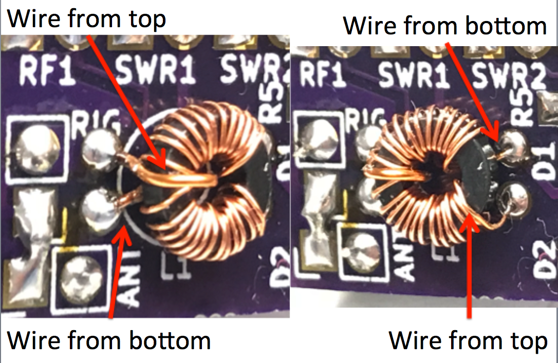
Put the toroid aside for now.
Now, solder the SMD components except for the trimmer, starting with the resistors, then adding the MiniMELF diodes and the SMD LED on the board. The two MiniMELF diodes have a colored ring that indicates the cathode. Mind the matching "K" on the PCB. The OSRAM SMD LED has a hardly visible cathode indicator: The respective edge is chamfered; you will need a good magnifying glass to see that.
Then add the trimmer. Finally, add the LEDs, mind the polarity. The rectangular pads on the PCB indicate the cathode (-, shorter leg). Depending on your preferred mounting style, you may need to bend the wires of the LED in a 90 degree angle close to the LED housing; be careful to not crack the cases. Do not bend the LEDs after soldering; this may create tiny cracks that will reduce their lifespan.
Hint: When you prepare the holes in the case of the rig before assembling the PCB, you can use these holes as a jig for aligning the LEDs in angle and position during soldering.
Finally, add the toroid.
Add wires to the ANT and TX pads. I recommend to use tightly twisted wire; it will have an impedance close to 50 Ohms. You could also try short pieces of RG174 coax.
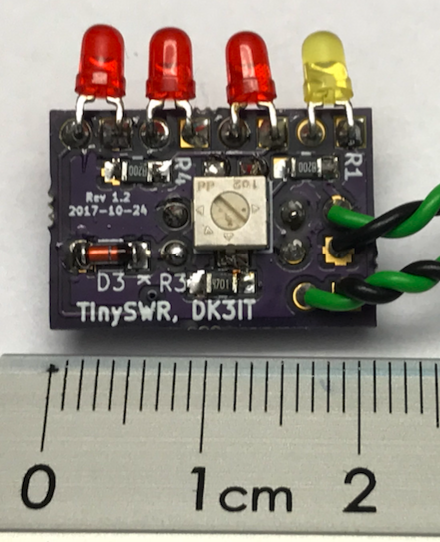
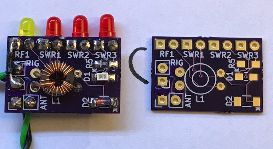
The following shows an assembled version of the PCB (version 1.2 dated October 24, 2017):
.
 .
.
Note that the orientation of several components changed in the various releases.
Connect the SWR meter to your QRP rig and attach a 50 Ohm dummy load to the ANT wires. Do use the power level you will most likely use for operating, but not more than 5 W of power! Now, turn the trimmer until only SWR1 continues to light a tiny little bit. Do not aim at turning it off completely, otherwise you might miss a high SWR.
Hint: This minimum can also be in the middle position of the trimmer potentiometer, i.e. do not expect it to be at either end of the trimming range.
If you are unable to get the other LEDs turned off, you have likely mixed the primary winding of the coupler. In that case, either swap the wires of the primary winding on the PCB, or, often easier, simply swap the ANT and TX wires.
Now you are all set! If less than two LEDs light up, your SWR should be less than 1:2. An SWR up to 1:1.3..1.5 will only light up the first LED. The brightness depends on the input power, unfortunately.
There is a minor bug in version 1.1 (2017-09-14) of the PCB that has been available via OSH Park from September 14 through October 24, 2017: The connection between the ground of antenna and rig on one hand and the SWR circuit is missing. Adding a short wire from the ANT GND (the rectangular pads) to any of the other pins that should carry GND (e.g. GND side of R3, R4, R5; cathode pins of SWR3 or RF1, or anode of D3) should do the trick.
The recommended way to fix this is a short wire from ANT GND to the rectangular pad of the yellow LED labeled RF1. The picture below shows this modification. Be careful not to shorten the "RIG" GND pin with the RIG signal pin.
Since the LEDs consume energy from the RF signal in a non-linear fashion, they may increase the amount of harmonic content in your transmitted signal. The full discussion is here; in a nutshell:
- the exact effect depends on the LEDs, SWR, power level, frequency, and more;
- it mostly affects the uneven harmonics, most relevant is the 3rd harmonic;
- the effect can be up to +5dB for the 3rd harmonic; that should normally not be a real problem, since a good transceiver will have them deep in the -60dB region, so even +5dB will not bring them above the required attenuation.
If you want to be on the safe side, check our transmitted signal after the installation of the TinySWR circuit with a spectrum analyzer.
An alternative is Vojtech's BlinkySWR, which takes extra measures for miniming the underlying effect (and operates in a digital fashion).
The files in the repository contain
- Gerber and drill files for producing your own PCBs, and
- a KiCad project with the schematics, PCB, and parts and footprints libraries.
KiCad is a great and free electronics design package. For more information, see http://kicad.org/.
The schematic is based on the design by Hans Steinort (DF3OS), see http://www.sp5jnw.sem.pl/konstrukcje/atudf3oshtm/atudf3oseng.pdf, with improvements from Dieter Engels (DJ6TE) and Hannes Hiller (DL9SCO). Thanks a lot!
THE DESIGN AND SOFTWARE IS PROVIDED "AS IS", WITHOUT WARRANTY OF ANY KIND, EXPRESS OR IMPLIED, INCLUDING BUT NOT LIMITED TO THE WARRANTIES OF MERCHANTABILITY, FITNESS FOR A PARTICULAR PURPOSE AND NONINFRINGEMENT. IN NO EVENT SHALL THE AUTHORS OR COPYRIGHT HOLDERS BE LIABLE FOR ANY CLAIM, DAMAGES OR OTHER LIABILITY, WHETHER IN AN ACTION OF CONTRACT, TORT OR OTHERWISE, ARISING FROM, OUT OF OR IN CONNECTION WITH THE DESIGN OR SOFTWARE OR THE USE OR OTHER DEALINGS IN THE DESIGN OR SOFTWARE.